Table of Contents
Renesas RZ/G1M iwg20m
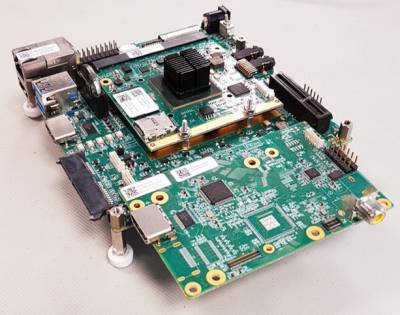
The iW-RainboW-G20D-Qseven development platform (iwg20m) is manufactured by iWave Systems Technologies and uses the Renesas RZ/G1M SoC. Full information about the platform can be found on the iWave Systems website.
The iwg20m development platform consists of four parts:
1) Renesas RZ/G1M (r8a7743) SoC
2) iWave iwg20m Qseven SoM
3) iWave iwg20d Qseven carrier board
4) iWave dbcm-ca HDMI/camera add-on board (optional)
From iWave Systems:
iWave's RZ/G1M development board incorporates RZ/G1M Qseven SOM Which is based on Renesas high performance RZ/G1M Dual ARM Cortex A15 MPU and the carrier board with optional 7” capacitive display kit. The development board can be used for quick prototyping of various applications targeted by the RZ/G1M processor. With the 120mm x120 mm Nano ITX size, the kit is highly packed with all the necessary on-board connectors to validate the RZ/G1M MPU features.
More information about the Renesas RZ/G1M SoC can be found on the Renesas website.
Building for the iwg20m Platform
Instructions on building the CIP SLTS Linux Kernel, the Renesas Yocto BSP and the Renesas SDK for the iwg20m platform can be found here.
Using the iwg20m Platform
This section provides information on using this reference platform.
The instructions assume that you are using the optional HDMI/camera add-on board. If you are not, please use change the device tree you use accordingly:
| Device Tree Blob | Platform Makeup |
|---|---|
| r8a7743-iwg20d-q7.dtb | r8a7743 iwg20m iwg20d |
| r8a7743-iwg20d-q7-dbcm-ca.dtb | r8a7743 iwg20m iwg20d dbcm-ca |
Switch Settings
On the iwg20d carrier board there is one set of switches - SW2 (BOARD CONFIG SW).
Default switch positions are in bold.
| SW Bits | SW2 Bit Name | OFF | ON |
|---|---|---|---|
| 1 | N/A | - | Set |
| 2 | N/A | - | Set |
| 3 | N/A | - | Set |
| 4 | N/A | - | Set |
| 5 | N/A | - | Set |
| 6 | PCIe_SELECT | PCIe channel0 is connected to Mini-PCIe Slot | PCIe channel0 is connected to PCIex4 Slot |
| 7 | DEBUG_SLECT | - | Debug Port is selected as UART |
| 8 | USB_ID | USB0 acts as Host mode or Device mode based on the connected cable in USB MicroAB connector (J2) | USB0 is forced to Host Mode |
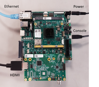
Connect to the board
Power Supply
Use the 12V power supply that comes with the platform and connect it to J4 (POWER JACK) at the top right of the platform.
Serial Console
Use a microUSB cable to connect the host PC to the iwg20m platform, using J3 (DEBUG PORT). It is routed to SCIF0 on the RZ/G1M via UART to USB convertor FT232RQ.
Virtual COM port (VCP) Windows drivers are available from the FTDI Chip website. Unless using a very old Linux distribution, all FTDI devices should be supported.
Serial settings:
- Baud rate: 115200
- Data: 8 bit
- Parity: None
- Stop: 1 bit
- Flow control: None
Any standard terminal emulator program can be used.
Notes
There are some connectors on the iwg20d carrier board that do not connect to the RZ/G1M SoC due to pin multiplexing choices. These connectors are:
- J24 (HDMI CONN) - If you would like to use HDMI output, please use the HDMI connector on the dbcm-ca add-on board.
- J23 (DUAL USB 3.0 CONN) - Only the lower USB 3.0 port is connected.
Booting the Kernel
To boot the board, flip SW1 (topright) to the 'ON' position. The following bootloader output should be seen on the debug serial console:
iW-RainboW-G20M SPI_LOADER(DDR3) V0.20 2015.07.16
 DEVICE SST25VF016B


U-Boot 2013.01.01 (Nov 04 2016 - 22:21:05)

CPU: Renesas Electronics R8A7743 rev 3.0
CPU: Temperature 25 C
Board: RZ/G1M iW-RainboW-G20M-Q7

DRAM:  1 GiB
MMC:   sh-sdhi: 0, sh-sdhi: 1, sh_mmcif: 2
SF: Detected SST25VF016B with page size 4 KiB, total 2 MiB
In:    serial
Out:   serial
Err:   serial

Board Info:
        BSP Version     : iW-PREWZ-SC-01-R3.0-REL2.0-Linux3.10.31
        SOM Version     : iW-PREWZ-AP-01-R3.0

Net:   ether_avb
Hit any key to stop autoboot:  3
Hit any key before the autoboot countdown expires to access the u-boot command line interface:
Hit any key to stop autoboot:  0
iWave-G20M >
You can now configure u-boot to boot into the Linux Kernel using the network, eMMC or SD card interfaces.
Common Settings
Some settings are the same, regardless of the boot medium used. In the u-boot serial console, enter the following commands:
setenv bootm_low 0x41e00000
setenv bootm_size 0x100000
setenv loadaddr 0x40007fc0
setenv fdt_addr 0x40f00000
TFTP/NFS
This section assumes that there are working TFTP and NFS servers on the host PC.
setenv ethaddr xx:xx:xx:xx:xx:xx
setenv ipaddr x.x.x.x
setenv serverip x.x.x.x

setenv bootcmd 'tftpboot ${loadaddr} /host/tftp/directory/boot/uImage; tftpboot ${fdt_addr} /host/tftp/directory/boot/r8a7743-iwg20d-q7-dbcm-ca.dtb; bootm ${loadaddr} - ${fdt_addr}'
setenv bootargs console=ttySC0,115200n8 ignore_loglevel vmalloc=384M rw root=/dev/nfs nfsroot=${serverip}:/host/tftp/directory ip=${ipaddr}
eMMC/SD Card
eMMC
(assuming that there are no SD cards plugged in)
setenv bootcmd 'mmc dev 2; ext4load mmc 2 ${loadaddr} /boot/uImage; ext4load mmc 2 ${fdt_addr} /boot/r8a7743-iwg20d-q7-dbcm-ca.dtb; bootm ${loadaddr} - ${fdt_addr}'
setenv bootargs console=ttySC0,115200n8 ignore_loglevel vmalloc=384M rw root=/dev/mmcblk0p1 rootwait rootfstype=ext4 rw
Micro SD connector on SoM (J2)
(assuming that there is only an SD card plugged in to J2)
setenv bootcmd 'mmc dev 1; ext4load mmc 1 ${loadaddr} /boot/uImage; ext4load mmc 1 ${fdt_addr} /boot/r8a7743-iwg20d-q7-dbcm-ca.dtb; bootm ${loadaddr} - ${fdt_addr}'
setenv bootargs console=ttySC0,115200n8 ignore_loglevel vmalloc=384M rw root=/dev/mmcblk0p1 rootwait rootfstype=ext4 rw
Full SD connector on bottom of carrier board (J30)
(assuming that there is only an SD card plugged in to J30)
setenv bootcmd 'mmc dev 0; ext4load mmc 0 ${loadaddr} /boot/uImage; ext4load mmc 0 ${fdt_addr} /boot/r8a7743-iwg20d-q7-dbcm-ca.dtb; bootm ${loadaddr} - ${fdt_addr}'
setenv bootargs console=ttySC0,115200n8 ignore_loglevel vmalloc=384M rw root=/dev/mmcblk0p1 rootwait rootfstype=ext4 rw


